After fitting a new Android head unit, powerfold mirrors and rear seat entertainment my next project was decided by my partner’s plaintive question of ‘where’s the clock’ when we were driving at night.
The P38 as standard has this in the dash:
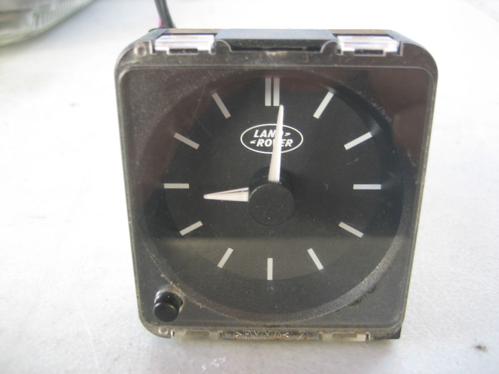
I think the face is supposed to light up at night, but mine never has, hence the complete lack of timekeeping once it’s dark.
I could have just fixed the light, but where would the fun be in that? I decided, instead, to design and build an arduino powered LCD Clock that can also (at some point in the future) display other things like…. temperature, car suspension height, anything else I can tap into.
I had a spare NodeMcu board lying around and debated whether to rely on my car’s internet connection to get the time from an NTP client. In the end I decided to use an RTC module, this one in fact.
For the screen, I needed something that would fit nicely into the space available (60mm by 55mm) and, after trying a 1.5″ OLED display eventually settled on a 1.8″ LCD. Getting that working was a bit of a pain initially, but after finding this incredibly helpful comment on amazon I got it going with no further problems.
The actual code was surprisingly straightforward. Using the Examples from the adafruit RTC library it was pretty straightforward to set / get the time from the RTC chip (see bottom of this post for the full code)
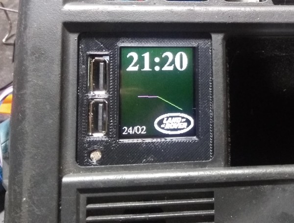
To display the time I played around with a few different formats but eventually settled on a simple 24 hour digital display and the current date, with an analog face just for added niceness. The analog code was blatantly ripped off from here and mangled to make something that works (that’s how I roll) and the final display looks something like this:

the circle on the bottom left is a light sensor, the display goes brighter in direct sunlight and dims when it’s dark, to avoid being dazzled at night.
On the left of the display are the outputs from a nifty 12v to usb board I found on ebay, by soldering some wires to the back of the USB ports I also pull 5v from this to power the board and LCD.
The enclosure went through several revisions, but now has an outer ‘shell’ and an interior panel that fits tightly into it, holding the LCD panel and light sensor in place. I’m quite pleased with this, no glue is required to assemble it and everything stays in place pretty well!
You can find the arduino code for this project here and the 3d printing files for the enclosure here
Hi, this looks amazing. Great work!
I’m extremely new at Arduino and I am trying to use this on a 1.8″ TFT LCD with no luck.. It comes up with the landrover logo full screen, with green background, the logo goes away, the green background stays and thats it, no clock etc. I’m not sure where to go from here.. please help!
I have changed the Baudrate to 9600 as per the instructions on my controller. and the serial monitor shows: “setup…”. then “updatedisplay” endlessly
Note- I have a slightly different display to the one you posted but i have had it working with other clock tutorial codes. – checked the connections are the same as whats defined. I have changed the code for LCD_18 to True, LCD_22 to false, wifi to true, entered my wifi details, and RTC to true. (i have the same RTC as shown in thingyverse. the LCD i have has no backlight connection- seems to be on all the time. but i cant see how this would matter.
anyways any ideas?
Cheers Nick